New suspension kit development progress information for Roadster (NA) ②
This time, even though it is a suspension kit for NA, I will delve into "Why was it based on NB?" ... from the viewpoint of bump stopper.For that purpose, it is necessary to imagine the relationship between the suspension spring and the bump stopper, so I will explain the relationship first.
 (1) Relationship between suspension spring and bump stopper
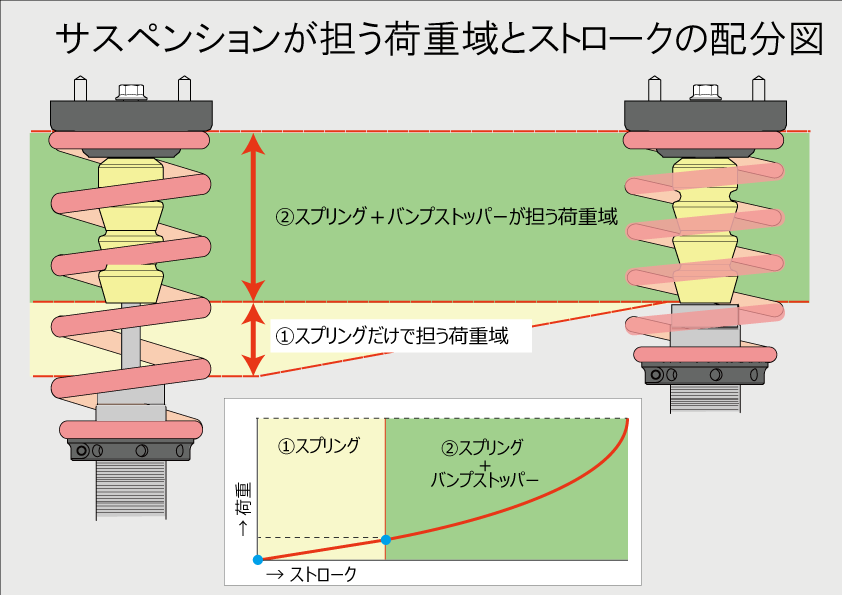
The suspension stroke mainly has "(XNUMX) load range carried by the spring alone" and "(XNUMX) load range carried by the spring + bump stopper".
When the stroke starts, the spring begins to contract and hits the bump stopper.As the stroke progresses, both the spring and the bump stopper contract, and finally the bump stopper strokes to the point where it becomes a rigid body that does not shrink any further.You can imagine that the point here is how to move from ① to ②.
Now let's take a look at the actual bump stopper.
(2) Difference between NB and NA bump stoppers.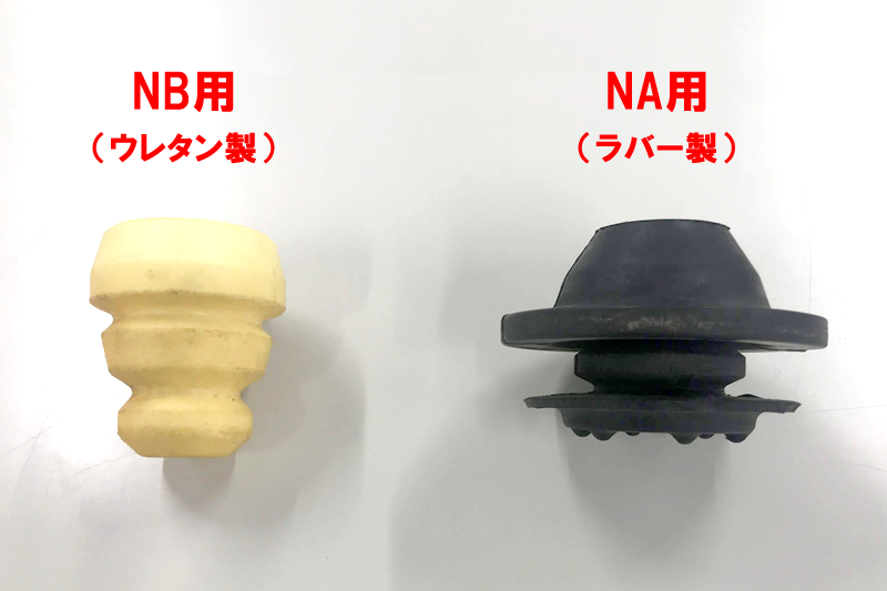
<For NB>
Made of urethane, it has a structure that easily expands and contracts.When crushed by hand, it shrinks with almost no resistance at first, and when crushed further, it gradually becomes harder, and finally it cannot be crushed by the force of the hand.
The structure is soft at the moment of bump touch and gradually hardens as the stroke progresses.
<For NA>
Made of rubber, it has a structure that is difficult to expand and contract.It hardly shrinks even if you apply force by hand.It is a structure that forcibly regulates the stroke so that the damper does not bottom out and break.
(3) Suspension stroke and distance to bump touch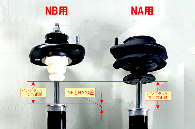
The stroke of the suspension is not the stroke amount until it touches the bump stopper (bump touch), but the stroke amount including 2.5G added to the suspension and the contraction of the bump stopper is compared. (By the way, NB and NA are almost the same.)
However, even if the stroke is the same, the distance to bump touch is different between NB and NA, and it can be seen that NB makes bump touch earlier than NA.Next, let's see what kind of effect it actually has, along with the characteristics of the bump stopper.
(4) Relationship between stroke amount and spring constant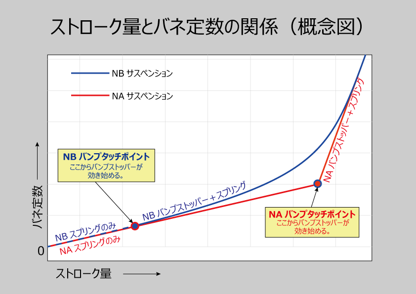
The graph on the right is a conceptual diagram showing the change in the spring constant with respect to the stroke amount.In the stroke distribution diagram above, the load range is assumed to be carried by each, but as the stroke progresses in both the spring and the bump stopper, "the load range increases = the spring constant in charge increases" ... the meaning is almost the same. Please think.
The point here is the change in the spring constant after passing the "bump touch point". The bump touch point of NB (blue line) is earlier than the stroke amount, but since the bump stopper shrinks flexibly, the spring constant will increase so as to draw a smooth curve even after passing the bump touch point. ..On the contrary, the bump touch point of NA (red line) is slower than the stroke amount, but since the bump stopper is hard, the spring constant rises linearly at a steep angle after passing the bump touch point.
Replacing this difference with actual driving, when you enter a curve and steer the steering, the roll starts and gradually deepens.The process of deepening the roll, that is, the behavior at the moment of passing the bump touch point, differs greatly between the two cars.
The NB naturally passes through the bump touch point, so the roll deepens without any discomfort.However, the NA will be stretched to some extent with only the spring until the bump touch, but at the moment of the bump touch, the spring constant will rise sharply and the behavior will be abrupt.
It's easy to see which one gives the driver a feeling of roll that meets the driver's expectations.Last upper mountIn addition, I think you can understand the reason why it was based on NB.
Once the specifications of the suspension kit have been decided, the next step is the practical edition.
First, determine the spring constant from the vehicle specifications, and derive the damping force in each speed range from the damping ratio of the AE flow.However, although it can be done to some extent with theoretical theory and experience, the last thing to rely on is not digital but our own sensitivity evaluation.It will be a while until the next update, but please look forward to it.
Posted by A.Asanuma